Eliot Chapel Stair Hall: A Study by Re-Creation
A Thesis Presented to the Division of the Arts Reed College
In Partial Fulfillment of the Requirement for the Degree Bachelor of Arts
Mark Guang-min Chen May 1995
This thesis is dedicated to my family.
Thanks to: Michael and Gerri for helping in any way they could, John Essick for being my fourth reader and rekindling my interest in physics, Minott Kerr for research assistance, Patrick the AV guy and the IMC people, Townsend Angell and the other people at Physical Plant, the other studio art seniors, Robin for putting up with me, Song Gong for always being there, and everyone else whom I might have forgotten.
Table of Contents
Influences
An introduction to what motivates my work, an overview of the historical background of the Stair Hall with a discussion of form and function, and a list of some influences
Method
A description of how the re-creation was accomplished, including a look at the octagonal bannister post and the wood paneling
The Script
An intricate look into the final animations
Installation
An explanation of the installation in the Chapel
List of Music and Other References
List of Illustrations
Figure 1: screenshot of Doom
Figure 2: screenshot of Myst
Figure 3: perspective Drawing -- left view from front door
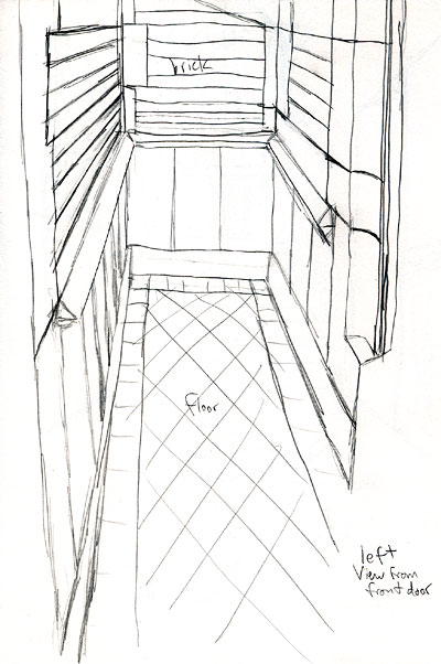
Figure 4: perspective Drawing -- view from northeast corner looking west
Figure 5: perspective Drawing -- view from southwest landing looking northeast
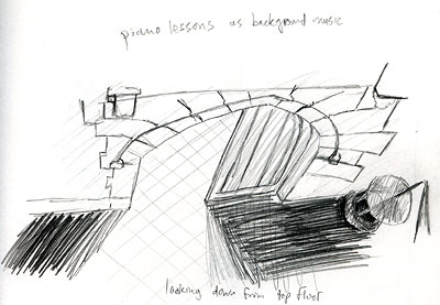
Figure 6: perspective Drawing -- looking down from top floor
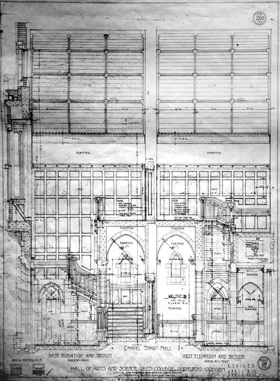
Figure 7: original architectural drawing by Doyle -- east and west walls
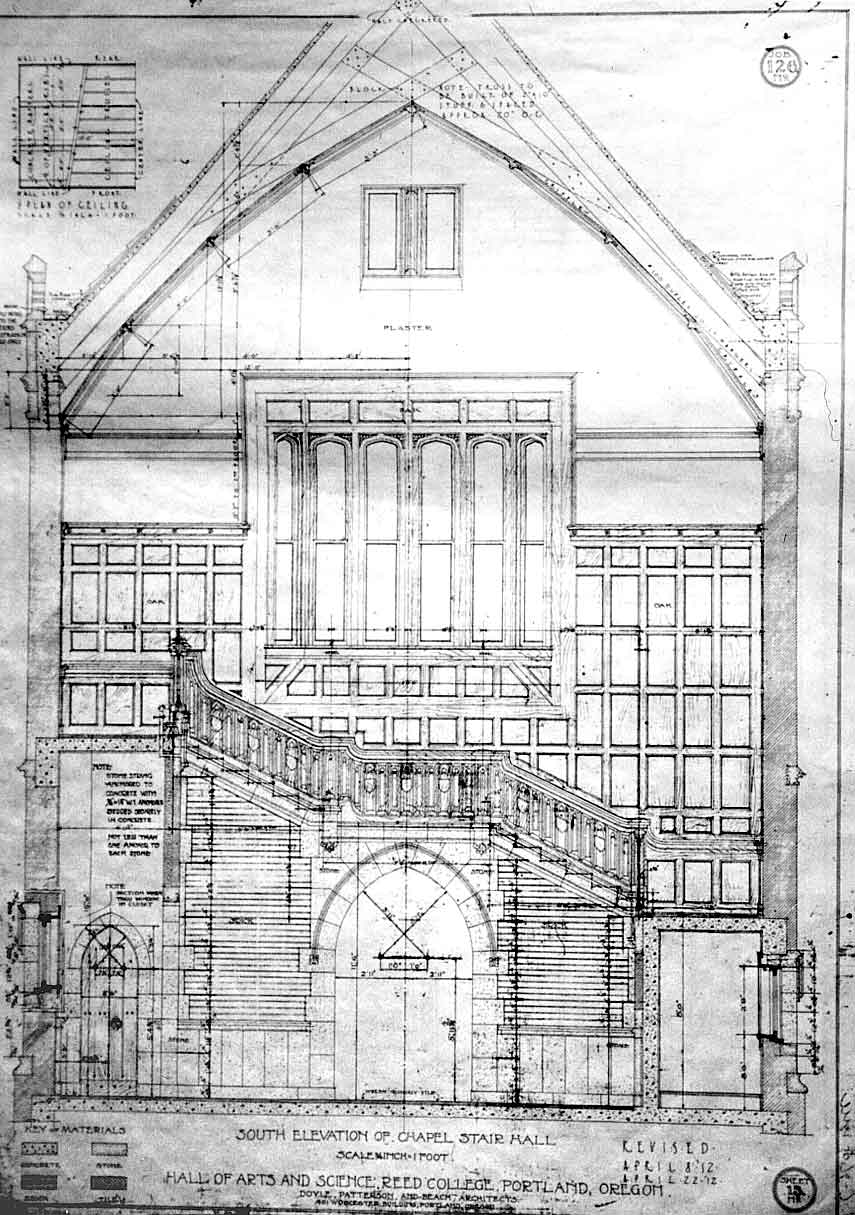
Figure 8: original architectural drawing by Doyle -- south wall
Figure 9: diagram for first set of stairs and its dimensions
Figures 10,11: details of the octagonal bannister post
Figure 12: diagram for the inner wall's different materials
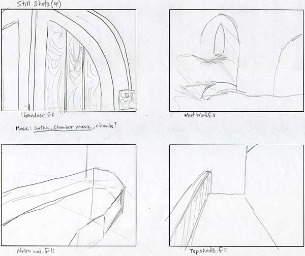
Figures 13-18: the story board used for the scripting of the animation
INFLUENCES
Overview
I like to take things apart to see how they are built and how each part interacts with the others. Each object serves a purpose and must be integrated into the whole to make a quality design. When an object meets the function requirement, looks graceful, and is easily used, then the design of it is successful. I also like to problem solve: figuring out how something works and which shapes to use in creating or re-creating an object. In other words, I like to put back together what I have taken apart, possibly more efficiently than the original. Using the computer to do this is challenging since I have to work with different materials and break each shape down to its simplest components, boxes, spheres, etc. It is important for the object that I choose to take apart and rebuild to be interesting enough to pose a challenge. It must also have a form that I think is pleasing to the senses. The Chapel Stair Hall met these requirements in that it is a space that provides transportation and produces a certain mood in the person being transported.
In re-creating it, however, note that I am not paying attention to some of the very specific details. Certainly, there are some, like the door handles, I am focusing on, but these are essential to the total intricacy of the space. This means the textures placed on each wall do not have to be in exactly the same pattern as the original site since the mere depiction of the texture is enough to capture the same feel. There are some patterns that are essential to the form, however, like the non-square stones that make up an archway, but the shape of the form and how each shape fits with the other shapes is the aspect of the form I am emphasizing.
I obtained copies of the original drawings that Doyle and his associates made and tried to make each of my objects with the same dimensions. Deciphering the elevation drawings is part of the process. One must be able to visualize how the two dimensional representations fit together to make a three dimensional space. The front door of the Stair Hall is a form that serves a purpose. I have studied how it opens and how the door closures work so that when I animate it on my computer it functions in the same way. This study of how things work doesn't simply apply to the mechanical, but also to anything visual. Later in the animation I have a sequence where the light changes to simulate different sun positions and weather conditions. Hopefully by capturing the visual feel of the Stair Hall, the mood that is caused by the space is also re-created.
Architecture
Christopher Alexander's book A Pattern Language provided me with an architectural framework for this project, in his conception of architectural form, purpose, and problem solving. He believes that to every function there is a perfect form, a pattern.
Each pattern describes a problem which occurs over and over again in our environment, and then describes the core of the solution to that problem, in such a way that you can use this solution a million times over, without ever doing it the same way twice.1
If he were to build a house, for example, before beginning a room he would analyze the purpose of the room and how it can be integrated into the purpose of the house. He would then list the required parameters for the specific purpose and find the pattern for that purpose. If the room performs two or more functions, it would require two or more patterns. Each function would require its own form. These forms add up to make the form of the room and the room forms add up to make the form of the house. It would seem that many forms would be repeated and many rooms would look the same. His theory of a pattern language does not constrain what the forms looks like, however, it only dictates how they function. The challenge in his design theory is to integrate the patterns in interesting and harmonious ways. The rooms that are individually designed fit together to make a house. The general purpose of the house must be met and so the rooms must be integrated successfully. An example of creating the right form for a purpose might be this: If you want an "in between" room, as in a room that serves as a buffer to another room which should slow down movement to prepare the "experiencer" for the next room, the placement of doors or entryways would be important. If the doors were lined up directly opposite each other the person walking through this room would not slow down. If, however, the door to the room was on the left side of the wall and the door leaving the room was in the opposite corner, then the walker would have to change his or her gait to reorient himself or herself.
In analyzing the Chapel Stair Hall and how it is used one gets the impression that it is more than just a means to transport oneself. It is also a place of meditation and ceremony. The space is always quiet and softly lit. The winding stairs keep the movement within contained to a small area and slows movement. The amount and intricacy of the detail keeps the space interesting enough for the experiencer to want to move slowly and quietly. The stairs are not essential to get to many important places on campus and are thus not very crowded. I have tried to re-create this mood in my animation.
Albert Ernest Doyle, a local architect of the early 1900s and chief architect of Eliot Hall, was a revivalist.2 Paul Timothy Pell states that there are two basic types of revivalists; those that revive a specific style and those that draw from any combination of styles, choosing which best fits individual commissions. Doyle was of the latter sort. When Doyle's firm, Doyle, Patterson, and Beach, was commissioned to plan the Reed College campus, he, the college president William T. Foster, and the board of trustees looked at many examples of earlier campus designs, most notably those of Oxford. The Tudor Gothic style of St. John's College received the most attention, but there were also influences from Foster's drawings of the men's dorms at Princeton, Patton Hall also at Princeton, Yale, and Skinner Hall at Mt. Holyoke College. Doyle must have preferred this Tudor Gothic style over other styles due to the message that came with it. Not only did this style have roots in the most respected colleges around the world, but it gave a sense of strong foundations and reverence. There were other styles that found their way into the design, however, like the pre-Elizabethan style stairs for the Stair Hall. Of the 49 buildings proposed for the campus, only three of the buildings were actually built; "Old Dorm Block," the Arts and Science Building, renamed Eliot Hall in the 1930s, and the library, which has recently been given a facelift.
Eliot Hall is constructed of reinforced concrete, limestone, and thick masonry walls laid in very strong "English Bond" style or in the "English Manner."3 The facade includes oriel windows and Gothic arches. There are many decorations, all of which have meanings attached to them, including the fleur-de-lys, symbolizing "the quest of France after beauty and truth," and Richmond roses, "symbols of Reed's ideals,"4 over entrances. Eliot Hall also has elements from the Pilgrim Inn of Glastonbury Abbey outside of London. The chapel is vaulted at various places by pointed and Tudor arches, and it appears that the design was influenced by the Canterbury Quadrangle at St. John's College. The Stair Hall shows influences from Westminster Abbey Church and the stairs themselves are copied after the spiral stairs used prior to the Elizabethan Era. The choice of styles was mostly directed to the purpose of the building: It is meant to "express strong ideals of scholarship." The seeming ease in which all the styles merge is a tribute to Doyle's revivalist approach. "Care of adaptation is shown in the great variety of doors and arches everywhere, all modeled from different sources but brought together into one harmonious whole."5 The level of ornamentation can also be attributed to Doyle's revivalist style, but it may also stem from the use of ornamentation as a means to denote something sacred or holy.
Most of the detailing of the chapel is attributed to a man named Charles Bernard Martin who worked under Doyle. It is possible that he also did the detailing found in the Stair Hall. Nothing, however, is known about the man. The Stair Hall was originally known as the Staircase of Emulation. The panels were made removable for later insertion of carved tablets honoring students (it seems none of us were ever honorable enough), and the brick walls are ready for bronze memorials. "The place in years to come is to be a memorial stairway."6 It is interesting to note that over the years the space has changed very little. Modern devices such as a fire alarm system, door closures, a bulletin board, and a fire escape route plans have been added to the Stair Hall, but these don't affect the mood or feel of the space much. They do, however, change the context of the space. They ground an otherwise timeless architecture into our time, the late 1900s. This may produce a minor disorientation, rather than actually orient the viewer, and give a feeling that something is not altogether "right" about the space. These are only apparent, though, when they are actually thought about. Simply passing through the space without paying any attention to the modern devices gives the same effect as if those devices were not there. From an historical stand point, it does give a means to date the space.
The Computer
By my use of the computer, it will be easy to date my thesis in the future due to the rapid change in technologies. Since the computer is a relatively new art tool, it may be necessary for me to explain how what I'm doing is creative rather than just a mechanical process. Certainly using the computer is much more constricted than using a pencil. Freedom is possible, but it is not as visible to those who are unfamiliar with using a computer. Most of the creative process, the excitement, comes when I discover how to create a complex object using a number of basic objects. A lot of it is trial and error. The finished product only contains all the work that I decided to keep. It does not chronicle the process. Sometimes when one draws on paper one becomes excited when the perfect line appears. Just the right stroke produces the right affect. So too in what I am doing. I'm not always sure what will happen when I perform a function on the computer. Sometimes very unexpected results occur which may be good accidents or bad accidents, just like in traditional drawing. At other times I know exactly what I'm doing and know the exact outcome before I perform a function. If something unexpected and unwanted happens, an advantage to computer art over traditional art is the "undo" function.
One of the most inspirational models for me is Antoine Predock, a contemporary architect working in New Mexico. He and his firm have been commissioned to design many houses and, more recently, buildings for educational institutions like Stanford University. My mother, one of Stanford University's few (due to major cuts) project managers, has had the good fortune of working with Predock on the new computer hardware building for Stanford. My family visited his office in Alberquerque in the winter of 1993 and he explained to us how he approaches each of his projects. Predock sees his designs as site-specific, in that they reflect the culture of the local community. His designs integrate purpose with elegance and meaning. The new building for Stanford University, for example, must be integrated with the campus' traditional Spanish architecture but must also reveal its function as a computer hardware building. His firm often creates computer images of what a building will look like, where the perspective lines intersect, and what patterns the form of the building will make. It was after looking at his work that I gained an interest in "computerizing" architecture.
There are many computer games that use high-end graphics today. Among these are true breakthroughs in virtual reality. Most are action or adventure games. An action game that uses a somewhat limited 3D engine is Doom by id Software.
Figure 1: Doom
The premise is pretty basic (shoot anything that moves), but the graphics sent shudders through the computer industry, not because of the detail, but because it was real-time7 and truly 3-D. The player moves in first-person perspective down hallways, through rooms, searching for objects to pick up that will help him or her survive. When people play this game their bodies actually move with the action. They move their heads lower so that they can see farther up and move their bodies so that the enemies don't hit them, even though these real actions have no effect in the game. This shows that the game has actually created a virtual world in which players believe themselves to be. I also want to create a space in which people believe themselves to be, with a level of detail that invites exploration by the viewer. Other games that depict more detailed worlds include Myst by Cyan and Broderbund. The Myst world is so detailed that it has become a sacred place and it invites curiosity and discovery.
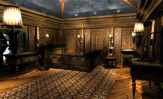
Figure 2: Myst
I wanted to emulate this level of detail with the Stair Hall. Myst, however, is not real-time user-controlled animation like Doom is. Instead it is a series of pre-generated still images depicting views several steps from each other placed one after the other to simulate movement through space. This, while animated, shows a very jerky movement from one place to another. I want my viewers to experience a smooth animated viewpoint like in Doom, but also see the level of detail achieved by Myst. By animated, I do not mean interactive. Interactive is when the user can control where the view goes. Instead, what I do is create preset animations, like a movie. The viewer is there only for the ride.
Video artists such as Nam June Paik have talked about the new media, the post-modern world where art is brought to the masses. This is not, as of yet, a reality in the U.S., but there is something appealing about the prospect of art reaching millions of people in their own living rooms. Therefore, I have chosen to output my work onto a VHS tape. This decision also allows for a soundtrack to be made to go along and help set the mood for the animation. Although, I plan to show the thesis in a specific installation, I am also considering passing out copies of the tape that I will be showing, thereby making the work accessible to many more people. The idea of free information is popular on the Internet nowadays, the Internet being a forum for any topic where any and all ideas are available. Many computer programmers and artists feel that their creations are also free to the public. Therefore, I plan on making still images of my thesis and uploading them to various sites in the Internet where anyone in the world who has the resources can view my work.
METHOD
|
Figures 3,4,5,6: perspective drawings of original site (click to enlarge) |
|
Figures 7,8: original architectural drawings by Doyle (click to enlarge) |
The first step that I took was to make drawings of the real site, some of which are included with this manuscript (Figures 3,4,5,6). These drawings were of flat walls to study the proportions of each wall and other objects attached to the walls like the stairs, doors, etc. and perspective drawings to help me understand the space. These perspective drawings provided me with something to compare my completed model with. I also went to the Physical Plant office and acquired the original elevation drawings that Doyle's firm made, two of which have been reproduced as well (Figures 7,8). Proportions of the different materials used for each wall were also taken. For example, on the wall with the front door, the south wall, there is a stone base, then brick, stairs, wood, and finally, stucco. There is a door in the bottom center, a door on the bottom left side, and two windows above.
After I made drawings of the walls, I then inputted them into my computer. To do this I used mainly four programs; a CAD program, a rendering program, an imaging program, and an animation editor. These were AutoCAD r.12, 3D Studio v.3, Photoshop 2.5 for Windows, and Autodesk Animator Pro. The CAD program was used to model the space. The rendering program was also used for modeling, but, most importantly, it was used to create lighting, create special effects, assign textures, create different viewing angles, and record the final animation. Photoshop was used to edit photographs that were scanned in and prepare them as textures to be laid onto the 3D models. The animation editor was used to string all of the different animation sequences together to make a whole piece.
I made a three-dimensional representation of the space combining all of the elevation views in AutoCAD and 3D Studio. To make my job easier I separated the space into different components so that I had many objects or entities making up the whole Stair Hall. These different objects depended on the material used. The wood paneling, for example, was one object while the stucco was another. I created the shape of an entity with the CAD program by simply plotting a series of vertices and connecting the dots (Figure 9). I then had to let the computer know where the faces of the object were. If I did not do this, an object that I create would only be a wire-frame model of the object; it would not be solid. Thankfully, there were some short cuts to this method in the form of "primitives," a tool found in the rendering program. These are preprogrammed shapes like boxes, cylinders, and spheres. For a box, I simply told the computer the length, width, and height, and the computer automatically drew all of the edges and vertices and filled in the faces. For a cylinder or sphere, I told the computer how many sides the primitive had and the radius (and length) of the object.8 While creating objects, I further broke them down according to which wall they were located on or associated with. The wood paneling for the south wall, in other words, was separate from the wood paneling found on the other walls, etc. Once I had a few individual objects I arranged them together to make a single wall, window, or staircase, and, eventually, when all of these larger parts had been created, the whole space was put together.
To give a more detailed example, I ask the reader to consider the octagonal post at the bottom of the stairs (Figures 10,11). This object was actually a combination of several parts, including two objects. The objects were the bottom base made of carved stone and the top made of wood. To make the bottom I created a cylinder with eight unsmoothed sides and many segments. I then scaled and moved some of the vertices of the segments so that an irregular "radius" or thickness was created. I did the same for the very top part of the wood object. For the middle part, the part with the arch design, I copied and pasted some pre-made sections of the bannister, rotated them 45º in relation to each other (from top-down view), and arranged them to form an octagonal shape. This copy and paste procedure was very helpful in creating many of the commonly found shapes. It was used extensively with the bannister, stairs, all of the different arches, and the wood paneling. I then took these three objects or groups of objects and arranged them so that the top part was on top, the bottom was at the bottom and grounded to the floor, and the middle was successfully holding the two ends together. I moved the whole post to its proper location and connected it to the existing bannister.
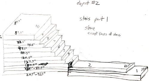
Figure 9: diagram for first set of stairs and its dimensions
The wood paneling is a good example of streamlining the creation process. I modeled the panels found above the landing, the north panels, first. I used AutoCAD for this. After I did this and integrated the north panels into 3D Studio, I found the rendering time and wait time9 to have greatly exceeded the times necessary previous to the wood panels addition. This was a dilemma. On the one hand, I wanted the full detail of all of the beveled edges so that if one were to get really close to the panels one would see very much detail. But on the other hand, if I were to create the panels with that much detail, it would take far more time to render and wait time for the whole piece in the long run than I had, considering that I had not even done the bannisters (the most detailed part of the space in terms of number of vertices and faces) by that time. I finally decided to simplify the wood paneling a little by using box-like forms instead of beveled boxes on some of the panels. I also decided that a very exact replication of the space was not necessary and that I could eye-ball it in many cases. The main shapes, like arches and doors, would have the right dimensions, but the details of the bannister and wood paneling were small enough that I could estimate their dimensions. I felt this was justified due to time constraints and the level of detail needed. Small details did not have to be exact because the animation concentrates on the space taken as a whole rather than looking at individual objects. There are some specific details that I wanted to look at, and for those I did model them exactly. After I had decided upon this more efficient course of action, I used 3D Studio to model the rest of the wood panels due to its use of primitives and the panels being made pretty much out of boxes.
Figures 10,11: details of the octagonal bannister post
The next job was solely done with the rendering program. I created lighting effects and I used virtual cameras so that the final output shows the view from one of those cameras. This allowed for a perspective view rather than an isometric or planar view. The computer gladly calculated the correct perspective according to the camera lens parameters that are set. I set them up with the default lens type to more closely resemble the human eye. If I wanted to, however, I could change the lens type and field of vision to create other interesting perspectives like a fish-eye view, etc. After light and camera set-ups were done, I assigned each object a texture or material. This was why a wall was broken down into different objects (Figure 12). It was easier to assign one texture to one object. To do this, however, I still needed the actual texture maps (images which are laid onto, or assigned to, an object).
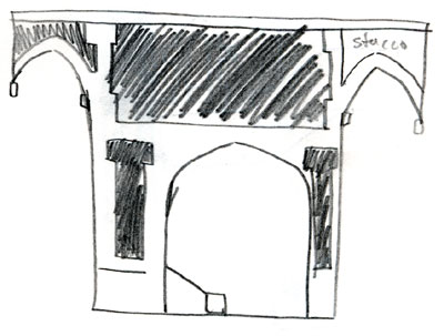
Figure 12: diagram for the inner wall's different materials
I went to the site and took photographs of the existing space. I took photos of the wood paneling, the brick, the stone, etc. I then scanned the photos into my computer. During the process of scanning them in (and due to my poor photography skills) I had to digitally touch up the images. I cropped them so that only one type of material was in each image. I resized and stretched them so that they are in the correct planar (as in flat on) perspective. I made the brightness of each image to be about equal to each other and made sure the right edge of each image matches up with the left edge and the top matches up with the bottom. In doing this when I use the images as patterns on an object or entity, it is not clearly visible where the patterns repeat. The quality of the photographs I took may cause some unease. I could have taken high quality photographs but I didn't think it was necessary since the main purpose was to study the shape of the space and not the specific textures, and the final image quality is severely limited due to my wish to animate the space. If I were to animate it with very high quality texture maps it would have taken weeks to render and would have used a lot of hard drive space.
After I had the texture maps I assigned them to their various objects and aligned the maps up correctly. The brick was in the traditional horizontal pattern, for example, not arranged diagonally. After all the textures were assigned, I then let the computer render the space. Actually, I rendered constantly to see if everything looked correct as I worked. With this I saw if lighting had to be different or if a particular texture map was too dark, etc. The big differences were then corrected to more closely match the original site. There were some exaggerations in the lighting made to emphasize certain patterns, such as those coming through the bannister.
I first did all the above steps with the front door, as a mini-study to get a better grasp of how long my task would take. Then when I completed the door (and decided that I had enough time to do the whole space this year) I worked on the stairs, the wood paneling, the bannister, the other doors, and everything else in roughly that order. As each of these parts was finished I combined it with the previously finished parts until finally they made the whole Chapel Stair Hall.
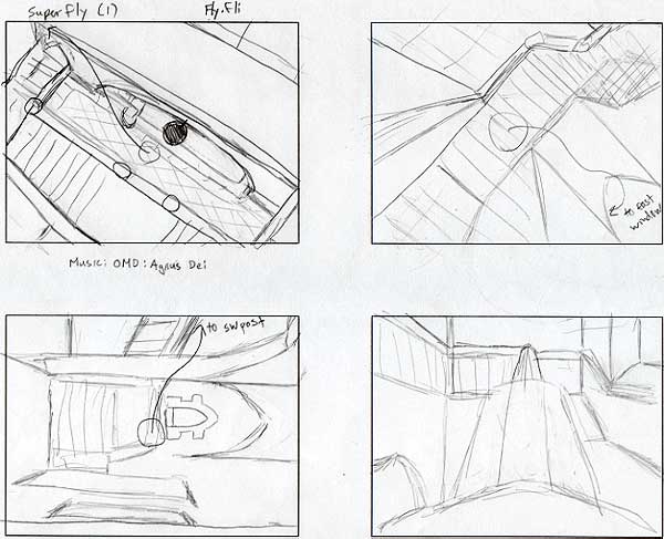
The next job was to animate and tinker with the completed model and settings. First I drew a story board on paper (Figures 13-18). Then I moved the camera position in key frames to follow the story board. So the camera started out at a certain place in frame 0, but I wanted it to end up at a different location in frame 30. I went to frame 30 and moved the camera to its new location. The computer then calculated all of the positions of the camera in the in-between frames. This is also how one animates lights and objects. I had to render each scene or sequence separately to later combine into one animation. I then wrote a script, or a mini program which was read by an animation player program, telling the computer the order in which the scenes were to be shown. I then played the script to see if everything ran smoothly. Then I played it again while recording with a VCR. At this time I also played an audio soundtrack which was recorded on the VCR.
 |
 |
 |
 |
 |
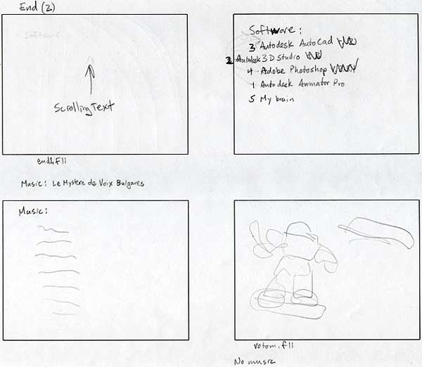 |
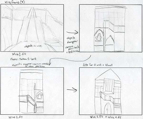
Figures 13-18: the story board used for the scripting of the animation (click to enlarge) |
|
The soundtrack was originally to be a recording of an actual performance in the chapel. Unfortunately, the quality of that recording and the music did not suit the work. Instead, I acquired other recordings from various sources at various times. A list is included following the bibliography. The choice of music may not be the most suitable since I know almost nothing of musical history or tradition. I chose the selection based on how I wanted the mood for each scene, not on whether the music was historically appropriate. The soundtrack starts with Gothic music, transforms to more modern music, and ends with Bulgarian dance music.
THE SCRIPT
The introduction has opening credits because I have created this thesis much like how I would produce a movie. SilverEdge Productions is a name that my brother and I have agreed to use whenever we produce anything computer related. (We hope to live off of each other's fame in the future.)
The first scene starts with a virtual walkthru as if the viewer were actually there walking, or gliding, up the stairs. The view moves around, as if the viewer were looking around, and concentrates on various specific perspectives or details. In doing this, I tried to simulate someone walking up the stairs to go to the chapel, and I tried to put myself in that situation. I thought to myself, "What would I look at if I were walking up the stairs, possibly for the first time, to the chapel?" I would look around to get the general layout down. Then I would look at where I was going and go there. Perhaps I would look back to see where I had entered. I would then look at the stairs while climbing the first few steps so as not to trip. As I walk up the stairs and come to a clearing (out from under the landing) I would have gotten used to the architecture of the stairs and feel enough confidence and curiosity to return my gaze to the whole of the space. Eventually, I would end up at the top of the stairs and I would want to look at the bay window once before leaving the Stair Hall to enter the chapel.
The second part of the animation is a break from the walkthru. It is sort of an intermission between the first part and the next part. It consists of a series of still views with animation representing movements that occur within the space. The first is of a view of the light coming from the sun through the bay window and the top window and of how the light changes throughout the day. This is the first of two studies of the same phenomenon and is seen from the top of the stairs just before the landing. The second scene shows the door opening and closing and also the light that comes through the archway when the door is opened. The last scene is of the light from the windows again, viewed from the top of the ceiling looking down onto the landing. This is particularly interesting to me as it clarifies the interaction between the light and the bannister.
The next scene, returning to an animated view port, will be from the perspective of a small particle, or a super-fly, zooming around the space. This serves two purposes. First it gives the opportunity to look at different perspectives or views of the Stair Hall that we humans cannot normally see. The second purpose is to completely disorient the viewer, hopefully enough to cause motion sickness, even though the viewer is not moving at all. I want to see if I can re-create the same physiological response to virtual reality that such games as Doom can have. The fly starts on the ceiling looking down, then moves ("flies") to the west end, south side of the topmost part of the bannister (just outside, but opposite of, Patrick's A/V office), weaving through the bannister on the way there, and faces the east wall. The fly looks around a bit and then moves to the east window, on the side of the window, looking at the west window, taking a diving action to get there. Finally the fly moves to the south-west post of the bannister (about 1/3 up the stairs), afterdoing a spin, and looks up the south part of the bannister, hopefully creating an interesting perspective and a launching point for the next animation sequence.
The space is now broken down into five parts, the four walls and the ceiling. This shows more clearly how the space was constructed on my computer. A non-shaded model of the room is shown during this sequence to more clearly understand the three dimensions of the space by letting the viewer see every material in full light. The east wall stays still, but the rest of the parts fold away to reveal an elevation view of the whole space, each wall lined up with the ceiling spread out over the top of the east wall, that should resemble the elevation drawings of Doyle and his associates. Note that there are extensions to some of the objects that I used (the wood paneling extends farther down than to the top of the stairs, for example). This was due to the fact that it was easier to model the space in layers, much like it is sometimes easier, in traditional painting, to paint a solid background and then cover the background with foreground objects. Hopefully this view clearly shows how the walls fit together to create the whole space. This is a graphic representation of how one fits the original elevation drawings together.
A wire frame three-quarter view of the entire space rotates in front of the camera clearly showing the proportions of the space. This study is important to understand how all of the objects are arranged to make the entire model.
A slower moving study of the walkthru and the fly are next. These show every tenth frame for two seconds per frame. This was done so the viewer could study the composition and detail of specific still images. It also gives one more time to digest the large amount information in some frames. After this is a faster study of the walkthru and fly view. These are meant as an experiment to see if physiological reactions can be produced in the viewer.
The last animation sequence to conclude the piece is simply a "slide show" of specific details of the space. For example, some materials in their raw form will be presented and the front door will be more closely looked at. This is followed by the end credits dedicated to the soundtrack and the software used. This is to avoid any legal hassles. Additional thank yous can be found at the beginning of this manuscript.
INSTALLATION
The chapel is equipped with its own projection screen and sound system. Taking advantage of this fact, I chose to show my thesis there, in a movie- like setting. The drawings by Doyle, Patterson, and Beach were hung in the Chapel Stair Hall since thechapel itself was too dark to view them. It took me a while to settle on how and where to install the show. At one point I wanted to build a booth in which someone would view three monitors showing different views of the Stair Hall. I discarded this idea because it would have taken too long and it would have added another level to my thesis which I did not think belonged there. I did not want this to be an installation piece like Bill Viola's installation in the Cooley Gallery. I wanted whatever is on the VHS tape to be the thesis, which can then be viewed anywhere. The final decision of the chapel was mainly due to location; one could experience the real Stair Hall before experiencing my Stair Hall.
CONCLUSION
The purpose of my thesis was twofold. The first sequence of animation was meant to re-create a preexisting space with the intention of capturing the same mood and feeling as the original. The way to do this was to copy the original's proportions, materials, and details, the form, and then to animate the space as if one were really there. There were many details or decoration that were left out because I felt it only necessary to include enough of the original to produce two effects: recognition and atmosphere/mood. Perhaps better terms for mood would be meaning and function/purpose. I wanted my piece to convey the same meaning and serve the same purpose as the original, as one of the preparatory spaces one travels through to the chapel. This means that the mood one feels must be one of ceremony, reverence, and elation. My piece is different than the actual site in that one is confined to the room that I have re-created. The same atmosphere is there though, and that is what I was going for. A question arises of the criteria used in deciding when there was enough detail. Where and why did I choose to place the cut-off points where they are? I am not fully prepared to answer these questions except to say that I intuitively sensed when there was enough detail to produce the same feeling as the original, not to mention allow recognition to those people who have been to the original. For further study, psychological and physiological readings on how people visually perceive their environment may be in order.
Once I re-created the space and all its emotional content, I broke it down to further study how the space was built, to more fully understand the three- dimensional relationships within it. This part of my thesis is clearly marked with a change in style of music and a change in the type of movement found in the visual animation.
In conclusion, I believe the thesis to have been a success. Not only did I produce the desired effect, but it far exceeded my personal expectations. I learned to appreciate the construction of buildings and their parts, and I gained a better understanding of three-dimensional volume. I also learned many tricks and short-cuts within the medium of the computer. The future applications of this method are many. I would like to create more spaces, but instead of re-creating an existing space, to design my own fantastical spaces. These creations would still refer to some existing space as I will probably use materials and decoration of existing spaces as models. This decision to create my own architecture is mostly due to the fact that with it comes more freedom to be creative. While the Stair Hall was a creative process-- problem solving-- it was a limited creativity. Most of the creativeness was from animating it after rebuilding it.
BIBLIOGRAPHY
1.Alexander, Christopher. The Timeless Way of Building. New York, New York: Oxford University Press, 1979.
2.__________. A Pattern Language. New York, New York: Oxford University Press, 1977.
3.Hall, Doug and Sally Jo Fifer, eds. Illuminating Video: An Essential Guide to Video Art. Aperture in association with the Bay Area Video Coalition, 1990.
4.Mitchell, William J. The Reconfigured Eye: Visual Truth in the Post- Photographic Era. Cambridge, Massachusetts: The MIT Press, 1992.
5.Norman, Donald A. The Design of Everyday Things. New York, New York: Doubleday, 1990.
6.Olson, Beatrice. "Under the Green Tiles." Griffin. Reed College, 1922.
7.Pell, Paul Timothy. The Architecture of Albert Ernest Doyle. Reed Thesis, 1976.
8.Ritz, Richard E., F.A.I.A. A History of the Reed College Campus and its Buildings. Portland, Oregon: Reed College Office of Publications, 1990.
9.Sikora, Paul Elliot. The Reed Campus: Conglomeration, Continuity and Harmony. Reed Thesis, 1970.
10.Stooss, Toni and Thomas Kellein, eds. Nam Jun Paik: Video Time, Video Space. New York, New York: H.N. Abrams, 1993.
11.Vaughan, Thomas and George A. McMath. A Century of Portland Architecture. Portland, Oregon: Oregon Historical Society, 1967.
12.Viola, Bill. Bill Viola: Selected Works. Los Angeles, California: Voyager Press, 1986.
LIST OF MUSIC AND OTHER REFERENCES
The Early Music Consort of London, "Hoquetus David, 3 voc.," Guillaume de Machaut, Hanover, West Germany: PolyGram, 1976.
__________, "Lasse! comment oublierary, 3 voc.," Guillaume de Machaut, Hanover, West Germany: PolyGram, 1976.
__________, "Interdeusas deserti meditans, 3 voc.," Anonmyous, Hanover, West Germany: PolyGram, 1976.
Fortran 5, "Crazy Earth," USA: Mute Records, 1991.
__________, "Groove," USA: Mute Records, 1991.
OMD, "Agnus Dei," McCluskey, Tye, and Shopsko, Beverly Hills, CA: Virgin Records, Ltd., 1993.
Unknown, "Polegnala e Todora," found on Le MystŠre de Voix Bulgares.
Myst is a trademark of Cyan, Inc. Copyright 1994, Broderbund Software, Inc., and Cyan, Inc.
Doom is a trademark of id Software.
FOOTNOTES
1Christopher Alexander, A Pattern Language (New York, New York: Oxford University Press, 1977), p. x.
2All information found in this paragraph and following paragraphs can be found in Pell's thesis, Sikora's thesis, Olson's article, or Ritz's book.
Beatrice Olson, "Under the Green Tiles," Griffin, (1922).
Paul Timothy Pell, The Architecture of Albert Ernest Doyle, Reed Thesis 1976.
Richard E. Ritz, F.A.I.A., A History of the Reed College Campus and its Buildings (Portland, Oregon: Reed College Office of Publications, 1990).
Paul Elliot Sikora, The Reed Campus: Conglomeration, Continuity and Harmony, Reed Thesis 1970.
3Pell calls it "English Bond" style and Sikora calls it "English Manner."
4Olson. Unfortunately she does not give any explanation to these claims.
7Real-time is a term used for games or other interfaces which respond as quickly as the user can input commands.
8Cylinders and spheres have an infinite amount of sides or faces due to their circular shape. Obviously, there is no way to render an infinite amount of faces. To get around this problem, the computer has a feature called "smoothing." The user inputs the number of sides depending on how detailed the particular shape or object is supposed to be and the computer then shades the edges as if they were not there. In other words, the shading on one face is gradually changed to match the shading on the adjacent face over the edge between the two faces.
9Wait time is a term that I use (I'm sure there's another standard term for this that I don't know about) when I'm referring to the time used in waiting for the computer to redraw a screen after a function is performed; zooming in and out, for example.